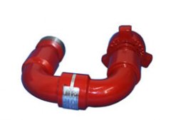
Swivel joint
|
Swivel joint |
|
|
 |
|
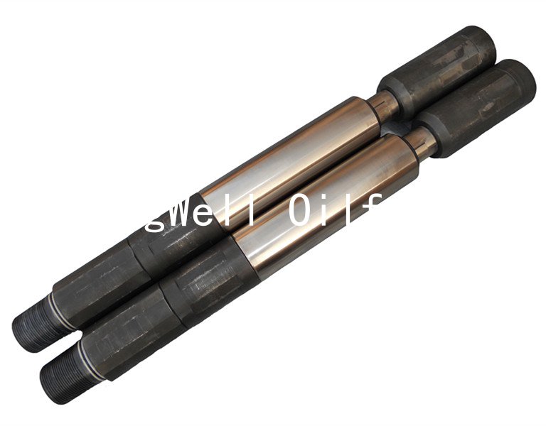
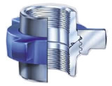
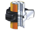
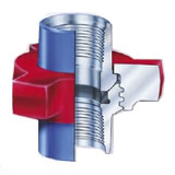
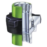
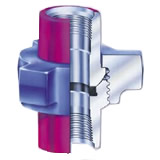
1.1.Product Overview
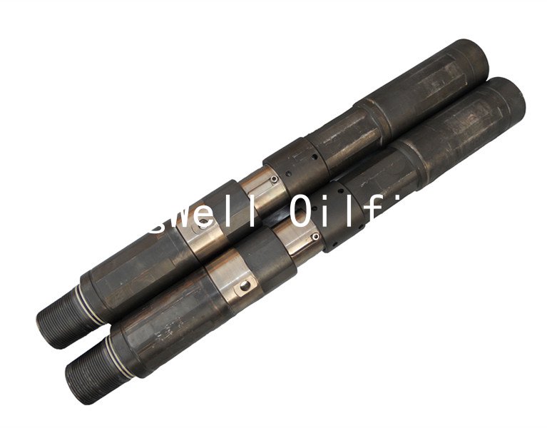
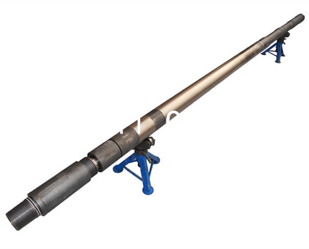
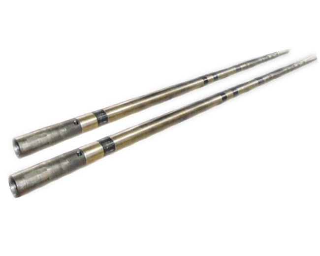
Swivel joint is cementing and fracturing equipment High Pressure Fluid Control Products. Hammer union is to change direction and to facilitate the construction of the pipeline connecting the pipe line connection.Widely used in the acidic operating environment (excluding containing CO2, H2S sour gas operating environment) in the high-pressure discharge line, input line, a temporary flow line, well testing, and other high-voltage transmission lines on pipelines. Swivel joint specifications are 1½ "~ 4" in, rated working pressure of 42MPa ~ 105MPa, working temperature -46 ℃ ~ 121 ℃.
⑴.The high pressure swivel joint has been widely applied in the condition of acid working, mainly including the high pressure discharge pipe, intake pipe, temporary flow pipe, well-testing pipe and pipes of fluid transportation under other high-pressure conditions;
⑵.The well-designed 1½ "~4" long sweep swivel joint possesses the cold working pressure of 42Mpa~105Mpa (6000psi~15000psi), with 10 different types. It can be rotated by 360° along one direction, two directions or three directions. The company can also provide 90 degree swivel joints with different types and repair kits under the conditions of normal temperature, low temperature and sulfurous gas.
2.Design Features
Swivel joint technical parameters and performance specifications are in line with API 6A. Its product specification level PLS3, performance levels for the PR2, it can work with SPM's similar products interchangeable.
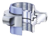
Swivel joint made of high strength alloy steel, special heat treatment process. It uses a unique trajectory, ball structure, to ensure a good rotation Swivel joint performance and impact resistance. Acme threaded connections, making it with the demolition convenient, fast, reliable connection, and reliable. Multiple seal design and high precision, to ensure the sealing performance of Swivel joint.
⑴.90 Degree swivel joint is connected with the hammer union, being characterized by the flexibility, fast tightening and disassembly, pressure-proof, sealing, convenient transportation and storage;
⑵.The long sweep swivel joint is designed by three lanes, which can effectively bear the heavy load and radial load to achieve the smooth pressure-bearing. The vibration of pipe will be minimized when bearing the variable loads;
⑶.All joint sizes are equally the same to the similar products of FMC in the well cementation and fracturing, being strong in the exchange;
⑷.Uniform wall thickness, long service life and smoother transportation of fluid;
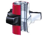
⑸.The sealing elements are made of hydrogenated nitrile butadiene rubber, with the good sealing performance;
⑹.The sealing elements are equipped with the metal spray ring, as well as the relief hold. In case of the leakage, the pressure will be relieved automatically to avoid its accumulation in the lane cavity;
⑺.The spot maintenance of high pressure swivel joint only requires the addition of lubrication oil occasionally to guarantee the normal operation.
3.Main Technical Parameters of swivel joint
⑴.90 degree swivel joint is connected with 10 type, 20 type,30 type, 40 type, 50 type, 60 type, 70 type,80 type, 90 type, 100 type union, and common connection modes are as below:

10 type(M×M) 10 type(F×M) 50 type(F×M) 50 type(M×M) 30 type(F×M)

100 type(F×M) 80 type(F×M) 100 type(M×M) 50 type(F×F) 20 type(F×M)
⑵.Common high pressure swivel joint specifications:
|
Name |
buckling size |
cold working press |
Terminal connection type |
Buckle model |
Model |
Long Sweep
Swivel Joint |
1½"
2"
3 "
4 "
|
42Mpa(6000psi)
70Mpa(10000psi)
105Mpa(15000psi)
|
screw thread(Tr100×12)
screw thread(Tr110×8) |
10 type
20 type
30 type
40 type
50 type
60 type
70 type
80 type
90 type
100 type |
fig602
fig1002
fig1502 |
M×M
M×F
F ×F |
Remark:①.The connection type of swivel joints can be design as users’ needs
②.“F”-threaded joint,“M”-sphere joint
③.How to place an order:3"×105Mpa(15000psi)-fig1502(F×M)-type10 |
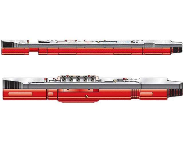
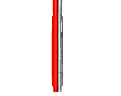
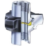
⑶.Example:Explosion photos of 3"×105Mpa(15000psi)-fig1502-M×M-10 type 90 degree Swivel joint

⑷.Example:Parts list of 3"×105Mpa(15000psi)-fig1502-M×M-10 type swivel joint
|
No. |
Name |
Qty |
|
No. |
Name |
Qty |
|
1 |
WN bent joint |
1 |
|
8 |
NQ straight joint |
1 |
|
2 |
Grease retainer ring |
3 |
|
9 |
Rand |
2 |
|
3 |
WQ straight joint |
1 |
|
10 |
Spring rand |
2 |
|
4 |
Steel ball |
297 |
|
11 |
Hummer union |
2 |
|
5 |
Greasy blockage |
9 |
|
12 |
Steel ball plug |
6 |
|
6 |
union sealing ring |
3 |
|
13 |
O-shaped sealing ring |
3 |
|
7 |
Gland packing |
3 |
|
14 |
Circlip for hole |
6 |
⑸.Each swivel joint is accompanied with a maintenance package. The maintenance package can also be ordered independently. Parts name and qty of long sweep swivel joint maintenance package
|
Name of maintenance package |
10 type
(Qty) |
20 type
(Qty) |
30 type
(Qty) |
50 type
(Qty) |
80 type
(Qty) |
100 type
(Qty) |
|
union sealing ring |
3 |
1 |
1 |
2 |
3 |
4 |
|
Spring rand |
|
Gland packing |
|
Circlip for hole |
|
Steel ball plug |
|
Steel ball |
|
Greasy blockage |
4.Precautions
⑴.Swivel joint must confirm the rated working pressure on the nameplate before use, applicable specifications, allowing the use of the temperature range.
⑵.The operator should take into account the drilling / or production operations will feel the temperature of the device, select the appropriate temperature, and the choice of the allowable temperature compatible Swivel joint.
⑶.Activities elbow have to undergo rigorous testing and nondestructive testing hydrostatic pressure in the factory. Disassemble or repair, you must be hydrostatically tested. Rated working pressure test pressure regulator 10 minutes, without leakage (Note: pressure test should be drained before the air in the system).
⑷Swivel joint should be regularly using ultrasonic thickness measurement of wall thickness, it is recommended once a month, if not reach the effective thickness value, should be replaced immediately. Replacement should be performed in conjunction with other pipelines.
⑸.Swivel joint can not operate in continuous or frequent rotation swing working condition; can not be immersed in water or working underwater. Can not withstand axial load elbow work activities.
⑹.When the installation Swivel joint, should fill seal grease, and manually check each joint rotation is flexible, without jamming. Operators should wear goggles to prevent the installation of a small debris flying eye injury.
5.Use methods and precautions
How to use:
⑴.Check all parts before use Swivel joint is flexible to use, it must be intact, in line with criteria to use;
⑵.Allowed pressure to meet the requirements of the construction process, not up to standard can not be used;
⑶Hand-tighten Swivel joint, adjusted to the desired angle and then hit with a pipe wrench to tighten or tighten.
Notes:
⑴.Put away after use to clean;
⑵.Always bearing oiling, rust-proof die.
6.Caveat
⑴.Do not use in excess of the rated working pressure conditions.
⑵.Swivel joint design operating temperature of -46 ℃ ~ 121 ℃, when the ambient temperature is below -46 ℃, or contact the fluid temperature is higher than 121 ℃, you should immediately discontinue use.
⑶.Do not disassemble Swivel joint work in the system pressure.
⑷Swivel joint less than the required thickness of the non-use, non-use of old and new with Swivel joint.
7.Transport
⑴.Swivel joint during transport, non-collision, to avoid the rain.
⑵.Swivel joint should be stored in ventilated, dry place, not the sun and rain. Forbidden contact with acid, alkali, salt and other corrosive substances.
8.Service
⑴.Under normal conditions of storage and use, starting six months from the date of shipment or product within three months, due to manufacturing quality and affect the normal use, the company responsible for free replacement or warranty.
⑵.Each product is accompanied by certificate, packing list and instructions.
⑶.You can order the appropriate product types according to the table. If you have special requirements, the company can design and manufacture.
⑷The company's products have any suggestions and criticisms, please fill in the "User Survey Form" to send a messag |
|
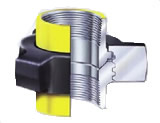
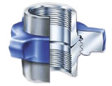
Hammer Union |
|
|
 |
 |
|
Thread hammer union |
Butt welding hammer union |
|
1.Product Overview
⑴.The hammer unions manufactured by our company is mainly used in cementing, crushing, acidifying, test and blocking, Kill line, high pressure manifolds and vehicle-mount system;Underground work is used to connect the various parts of the pipeline construction. Flexible operation, high voltage and other characteristics;
⑵.The high pressure wing union designed and manufactured by our company includes thread union and welding union, with specification 1"~12" and cold working pressure 14Mpa-105Mpa (2000ps-15000psi);
⑶.High pressure hummer union is marked with apparent connection buckle and pressure rating;
⑷.The anti-sulfuretted hydrogen hammer union is workable under acid environment and shows grass green.
2.Design Features
⑴.With precise ball surface and 90 degree conical surface processed by precise machine, Wing hammer union is of high strength and pressure-bearing capacity;
⑵.The LP thread, UN thread, EU thread, processed by numerically-controlled machine and imported cutter, has high precision and strong sealing, ensures high press and sealing;
⑶.The seal ring is made by imported sizing material. The seal ring can keep strong sealing for joints and avoid joints from corrosion, and prolong the product life;
⑷.The wing hammer union which specially applicable to acid environment is designed and manufactured in strict accordance with NACE MR0175;
⑸.Wing unions joints are all ACME thread, thus it is easy to assemble, disassemble without any tools and it has self-lock function. The product parts are universal internationally and can be exchanged.
3.Use Method
⑴.First Hammer union threaded check again, if the threading dislocation fracture buckle phenomenon should be replaced.
⑵.Check, install rubber seals;
⑶.Hammer union with a wire brush to clean brush and apply sealant on the threads after connecting tubing or size in the head with a pipe wrench to tighten, then use a hammer to hit the tight prison or on the tube hit the clincher.
4.Precautions
⑴ when hit with a hammer and smashed Hammer union to prevent thread.;
⑵. After use should be promptly cleaned up on the workbench.
5.Common Buckle Models for High Pressure wing unions
 |
 |
 |
 |
|
fig100 union |
fig200 union |
fig206 union |
fig211 union |
 |
 |
 |
 |
|
fig400 union |
fig600 union |
fig602 union |
fig1002 union |
 |
 |
 |
|
|
fig1003 union |
fig1502 union |
fig2202 union |
|
6.Main Technical Parameters for Hammer Union
|
Production name |
specification |
cold working press |
working environment |
buckling size |
|
Normal |
anti-sulfur |
1 " |
1¼ " |
1½ " |
2 " |
2½ " |
3 " |
4 " |
5 " |
6" |
8" |
10 " |
12 " |
|
Thread
hammer union
butt welding
hammer union
|
fig100 |
1000psi |
√ |
|
|
|
|
√ |
√ |
√ |
√ |
√ |
√ |
√ |
|
|
|
fig200 |
2000psi |
√ |
|
√ |
√ |
√ |
√ |
√ |
√ |
√ |
|
|
|
|
|
|
fig207 |
2000psi |
√ |
|
|
|
|
|
|
√ |
√ |
|
√ |
√ |
√ |
|
|
fig211 |
2000psi |
√ |
|
√ |
√ |
√ |
√ |
√ |
√ |
√ |
|
|
|
|
|
|
fig400 |
2500psi |
√ |
√ |
|
|
|
|
|
|
|
√ |
√ |
√ |
√ |
√ |
|
fig400 |
4000psi |
√ |
√ |
|
|
|
√ |
√ |
√ |
√ |
|
|
|
|
|
|
fig600 |
6000psi |
√ |
|
√ |
|
√ |
√ |
√ |
√ |
√ |
|
|
|
|
|
|
fig602 |
6000psi |
√ |
√ |
√ |
√ |
√ |
√ |
√ |
√ |
√ |
|
|
|
|
|
|
fig1002 |
10000psi |
√ |
√ |
√ |
√ |
√ |
√ |
|
√ |
√ |
√ |
√ |
|
|
|
|
fig1003 |
10000psi |
√ |
√ |
|
|
|
√ |
√ |
√ |
√ |
√ |
|
|
|
|
|
fig1502 |
15000psi |
√ |
√ |
√ |
|
√ |
√ |
|
√ |
√ |
|
|
|
|
|
|
fig2202 |
15000psi |
|
√ |
|
|
|
√ |
|
√ |
|
|
|
|
|
|
How to place an order:Thread hammer union-fig1502-3"×15000psi
|
|
|
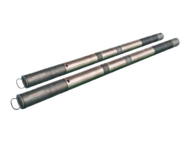
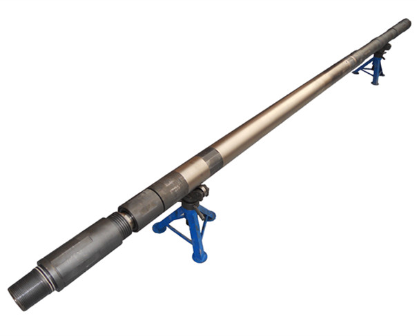
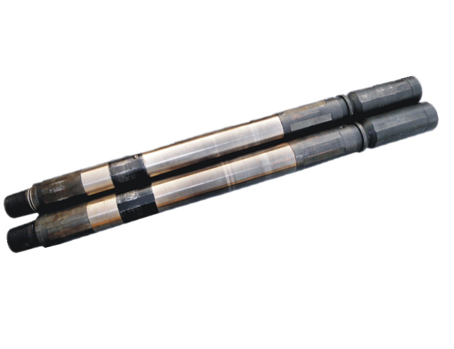
Pup Joint |
|
|
 |
|
1.Product Overview
Pup joint is cementing and fracturing equipment delivery High Pressure Fluid Control Products. Widely used in the acidic operating environment (excluding containing CO2, H2S sour gas operating environment) in the high-pressure discharge line, input line, a temporary flow line, well testing, and other high-voltage transmission lines on pipelines. Pup joint specifications are 1 in ~ 4 in, length 0.5 m, 1 m, 1.5 m three kinds, rated working pressure 42MPa ~ 105MPa, working temperature -46 ℃ ~ 121 ℃.
⑴.The high pressure pup joint designed and manufactured by our company is forged by high quality structural alloy steel. Terminal union is forged together with pipe, which is able to avoid disassembling and ensure good sealing, small weight, convenient use and fast installation. high pressure Pup joint has various specifications including 1"~4" and lengths including 1’, 2’, 3’, 4’, 5’, 6’etc, rated working pressure is 42MPa~105MPa. Any specification of pup joint or even integral pup joint special for acid environment is available according to users’ needs;
⑵.Except for integral pup joint, our company is also supplying pressure thread sealing pup joint, non-pressure thread sealing pup joint and welding pup joint.
2.Design features
Pup joint technical parameters and performance specifications are in line with API 6A. Its product specification level PLS3, performance levels for the PR2, it can work with SPM's similar products interchangeable.
Pup joint made of high strength steel, with a special toughening process. It uses Acme threaded connection, making it with the demolition convenient, fast, reliable connection, and reliable. Multiple seal design and high precision, to ensure the sealing performance of Pup joint.
⑴.The integral pup joint is union instead of screw connection on the top, which is more secure and reliable;
⑵.Easy and quick assembling and disassembling;
⑶.High strength and low weight;
⑷.Each technical parameters and performances of pup joints conform to standards of API Spec 6A and can be exchanged with like products internationally.
3.Main Technical Parameters of high pressure Pup Joints
|
Production name |
Terminal connection type |
Buckle model |
Working environment |
Buckling size |
|
Pressure thread sealing pup joint |
Tr100×12
Tr110×8 |
42Mpa(6000psi)
70Mpa(10000psi)
105Mpa(15000psi)
|
1½ "
2"
3"
4" |
|
Non-pressure thread sealing pup joint |
|
Integral pup joint |
Union head fig602
Union head fig1002
Union head ffig1502 |
M×M
M×F
F×F |
|
Anti-sulfur integral pup joint |
|
Welding pup joint |
|
Welding flange pup joint |
Flange |
2-1/16"
2-9/16"
3-1/16"
3-1/8"
4-1/16" |
Remark:①.“F”-threaded joint,“M”-sphere joint
②.How to place an order:Integral pup joint-fig1502-M×F-3"×105Mpa(15000psi) |
|
4.Precautions
⑴.Must be confirmed before Pup joint from the nameplate rated working pressure, applicable specifications, allowing the use of the temperature range.
⑵.The operator should take into account the drilling / or production operations will feel the temperature of the device, select the appropriate temperature, and the choice of the allowable temperature compatible Pup joint.
⑶.Pup joint undergo a rigorous hydrostatic testing and non-destructive testing in the factory. Disassemble or repair, you must be hydrostatically tested. Rated working pressure test pressure regulator 10 minutes, without leakage (Note: pressure test should be drained before the air in the system).
⑷.Pup joint should regularly measure the wall thickness using ultrasonic thickness gauge is recommended once a month, if not reach the effective thickness value should be replaced immediately. Replacement should be performed in conjunction with other joints.
⑸.Pup joint work can not be immersed in water or underwater; can not bear axial load at work.
⑹. When the installation, the operator should wear protective goggles to prevent the installation of a small debris flying eye injury.
5.Caveat
⑴.Do not use in excess of the rated working pressure conditions.
⑵.Pup joint design operating temperature of -46 ℃ ~ 121 ℃, when the ambient temperature is below -46 ℃, or contact the fluid temperature is higher than 121 ℃, you should immediately discontinue use.
⑶.Do not disassemble Pup joint work in the system pressure.
⑷.Pup joint less than the required thickness of the non-use, non-use of old and new with Pup joint.
6.Transport and storage
⑴.Pup joint during transport, non-collision, to avoid the rain.
⑵.Pup joint should be stored in ventilated, dry place, not the sun and rain. Forbidden contact with acid, alkali, salt and other corrosive substances.
7.Service
⑴.Under normal conditions of storage and use, starting six months from the date of shipment or product within three months, due to manufacturing quality and affect the normal use, the company responsible for free replacement or warranty.
⑵.Each product is accompanied by certificate, packing list and instructions.
⑶.You can order Pup joint depending on the size of diameter and length. If you have special requirements, the company can design and manufacture.
⑷.The company's products have any suggestions and criticisms, please fill out the back of the "User Survey Form" and send emails.
|
Integral Fitting |
|
|
 |
 |
 |
 |
|
Long sweep elbow |
Right angle elbow |
Tee |
Y-tee |
 |
 |
 |
 |
|
Manifold tee |
Cross tee |
Manifold cross |
Fishtail fitting |
|
|
|
|
|
 |
 |
 |
|
|
Adjustable fitting |
Flange fitting |
Plug |
|
|
1.Product Overview
Integral fittings are cementing and fracturing equipment High Pressure Fluid Control Products. Widely used in the acidic operating environment (excluding containing CO2, H2S sour gas operating environment) in the high-pressure discharge line, input line, a temporary flow line, well testing, and other high-voltage transmission lines on pipelines. There are high-voltage connector specification 2in ~ 4in, rated working pressure 42MPa ~ 105MPa, working temperature -46 ℃ ~ 121 ℃.
Integral fittings technical parameters and performance specifications are in line with API 6A. Its product specification level PLS3, performance levels for the PR2, it can work with SPM's similar products interchangeable.
⑴.High pressure integral fittings can connect with all kinds of crushing and cementing equipments at spot;
⑵.Integral manifold joint includes long sweep elbow, right angle elbow, Tee, Y-tee, manifold Tee, cross tee, manifold cross, integral fittings with specifications of 2’’, 3’’ and cold working pressure 42MPa~105MPa(6000Psi~15000Psi).
2.Design Features
⑴.Integral fittings are made by high-strength alloy steel characterized by high pressure bearing and long life span;
⑵.After heat treatment hardening and tempering, it shows good surface gloss;
⑶.Thread is made by imported tooling, thus it has good sealing;
⑷.The terminal end is connected by union, which ensures convenient and fast use.
3.Common Buckle Models for Integral Fittings
|
Production name |
buckling size |
working environment |
Buckle model |
|
long sweep elbow |
2"
3" |
42Mpa(6000psi)
70Mpa(10000psi)
105Mpa(15000psi) |
F×M、M×M、F×F、Welding type |
|
right angle elbow |
|
Tee |
FMF、FMM、FFM、FMF、MMM、FFF、Welded fitting |
|
Y-tee |
MFF、Welded fitting |
|
manifold tee |
MFF、FFF、Welded fitting |
|
cross tee |
FFFF、FFMF、FFMM、FMMM、FMMF、MMMM、Welded fitting |
|
manifold cross |
MFFF |
|
integral fitting |
2" ×3"
2" ×4"
3" ×4" |
Terminal connection type:
fig602-fig1002
fig602-fig1502
fig1002-fig1502 |
Adapter:F×M、F×F、M×F、B×F、
M×P、flange fitting×union、Welded fitting |
Remark:①.Each terminal end of Integral fittings can be customized in size (reducing nipple)
②.“F”-threaded joint,“M”-sphere joint,“B”-Internal thread,“P”-male thread
③.How to place an order:cross tee-3"×105Mpa(15000psi) - FFMM |
|
4.Precautions
⑴. Integral fittings must confirm the rated working pressure for the specifications on the nameplate from the front, allowing the use of the temperature range.
⑵. the operator shall take into account the drilling / or production operations will feel the temperature of the device, select the appropriate temperature, and the choice of the allowable temperature compatible Integral fittings.
⑶, Integral fittings have to undergo rigorous hydrostatic testing and non-destructive testing in the factory. Disassemble or repair, you must be hydrostatically tested. Rated working pressure test pressure regulator 10 minutes, without leakage (Note: pressure test should be drained before the air in the system).
⑷, Integral fittings should be regularly using ultrasonic thickness measurement of wall thickness, it is recommended once a month, if not reach the effective thickness value should be replaced immediately. Replacement should be performed in conjunction with other pipelines.
⑸, Integral fittings can not be immersed in water or underwater work; you can not bear the axial load at work.
⑹, the installation, the operator should wear protective goggles to prevent the installation process has small fragments flying eye injury.
5.Caveat
⑴. Do not use in excess of the rated working pressure conditions.
⑵.Integral fittings designed operating temperature of -46 ℃ ~ 121 ℃, when the ambient temperature is below -46 ℃, or contact the fluid temperature is higher than 121 ℃, you should immediately discontinue use.
⑶. Do not disassemble Integral fittings in the system working pressure.
⑷.Integral fittings less than the required thickness of the non-use, non-use of old and new with Integral fittings.
6.Transport and storage
⑴.Integral fittings during transport, non-collision, to avoid the rain.
⑵.Integral fittings should be stored in ventilated, dry place, not the sun and rain. Forbidden contact with acid, alkali, salt and other corrosive substances.
7.Service
⑴. Under normal conditions of storage and use, starting six months from the date of shipment or product within three months, due to manufacturing quality and affect the normal use, the company responsible for free replacement or warranty.
⑵. Each product is accompanied by certificate, packing list and instructions.
⑶. You can order Integral fittings depending on the size of diameter. If you have special requirements, the company can design and manufacture.
⑷. The company's products have any suggestions and criticisms, please fill out the back of the "User Survey Form" and send emails.
----------------
|
Plug valve |
|
|
 |
") |
|
1502 Plug valve |
Plug valve(F-F) |
") |
 |
|
Plug valve(M-M) |
Plug valve |
|
1.Product Overview
I produced the specification level Plug valve products for PLS3, performance levels for PR2, which can be of similar products with SPM's interchangeable equipment widely used in cementing and fracturing equipment.
⑴.High pressure plug valve is a very important fitting for cementing, well cementing and crushing and is also applicable to control other high pressure fluid. Plug valve is combined by valve body, seal arcing segment, plug cock, etc.
⑵.The low torque and high pressure plug valve designed and manufactured by our company are all made by high quality and high strength structural alloy steel. Strict heat treatment ensures even metallographic structure and loading capacity. The materials completely conform to USA ASTM and AISI standards and products technical index fully matches with API Spec 6A standard. Product joints can be connected by joint thread, pipeline thread, butt welding or non-pressure sealing end;
⑶.There buckle models are provided for the terminal of plug valve: union plug valve, LP female connection and LP external thread. In according to users’ needs, we can design the high pressure plug valve with a base;
⑷.High pressure plug valve has different specifications: 1’’, 2’’, 3’’ and different cold working pressures: 42Mpa(6000Psi)、70Mpa(10000Psi)、105Mpa(15000Psi). Plug valve and maintenance package used under normal temperature, low temperature and sulfurous gas environment are available.
2.Design Features
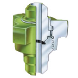
Plug valve from the valve body, cocks, seals and other parts arc pieces (see the specific one). Its working principle is: By adjusting the position of the tap handwheel for control flow size. Between the body and cock, sealed arc chip seal, seal arc due to the high precision sheet, and using a special grinding process to ensure that products in the high-pressure working conditions are not leaking.
⑴.Stable pressure-bearing: equipped with changeable elastic nitrile rubber sealing ring, firm wall thickness; it is able to bear pressure under high pressure line;
⑵.Convenient to exchange: union joints on both ends and can be exchanged with LP, UN internationally due to inch size is applied;
⑶.Simple maintenance: it is unnecessary to dissemble from pipeline to maintain or repair plug valve, and no need to use special tools in case of disassembling;
⑷.Good sealing and preservation: the plug cock is fine finished by special coating technology;
⑸.Visible valve position: the symbols of fully open and close of valve are clearly marked on the plug cock cap. The tripping spring restricts valve in proper positions.
3.Main Technical Parameters of Plug valve
⑴.High pressure Plug valve
|
Specifications |
buckling size |
cold working press |
Terminal connection type |
Buckle model |
SF42
SF70
SF105 |
1"×2"
2"×2"
3"×3" |
42Mpa(6000psi)
70Mpa(10000psi)
105Mpa(15000psi) |
Internal thread ,External thread(LP、NU) |
union fig1002
union fig1502
union fig602 |
M×M
M×F
F ×F |
Remark:①“F”-threaded joint,“M”-sphere joint;“LP”-pipe thread, “UN”-un-thickening tubing thread
②How to place an order:SF105-M×F-2"×2"-fig 1502 union plug valve |
⑵.Example:SF105-M×F-2"×2"-fig 1502 Structure of union plug valve
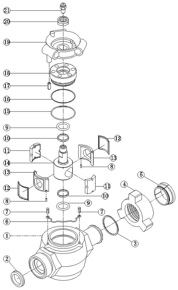
⑶.Parts list of (FXM) high pressure fig plug valve
|
No. |
Name |
Qty |
|
No. |
Name |
Qty |
|
1 |
Valve body |
1 |
|
12 |
Square sealing ring |
2 |
|
2 |
Sealing washer |
1 |
|
13 |
Sealing arcing shim |
2 |
|
3 |
Spring rand |
1 |
|
14 |
Plug cock |
1 |
|
4 |
Wing union |
1 |
|
15 |
Valve deck sealing ring |
1 |
|
5 |
Rand |
3 |
|
16 |
Support band of valve deck sealing ring |
1 |
|
6 |
Retaining spring |
1 |
|
17 |
Elastic cylindrical pin |
1 |
|
7 |
Retaining pin |
2 |
|
18 |
Valve deck |
1 |
|
8 |
Locating pin |
2 |
|
19 |
Plug cock cap |
1 |
|
9 |
O-shaped sealing ring |
2 |
|
20 |
Locknut |
1 |
|
10 |
Sealing ring support band |
2 |
|
21 |
Grease fitting |
1 |
|
11 |
Side arcing shim |
2 |
|
|
|
|
⑷.High pressure plug valve maintenance package parts are shown as 9,10,11,12,13,14,15,16 and 21 in structure of high pressure plug valve.
List of fig plug valve maintenance package
(overseas products in the same specification can be replaced by maintenance package)
|
Name |
1"×2"plug valve |
2"×2"plug valve |
3"×3"plug valve |
|
Qty
|
105Mpa
15000psi |
70Mpa
10000psi |
42Mpa
6000psi |
105Mpa
15000psi |
70Mpa
10000psi |
42Mpa
6000psi |
105Mpa
15000psi |
70Mpa
10000psi |
42Mpa
6000psi |
|
O-shaped sealing ring |
2 |
2 |
2 |
2 |
2 |
2 |
2 |
2 |
2 |
|
Sealing ring support band |
2 |
2 |
2 |
2 |
2 |
2 |
2 |
2 |
2 |
|
Side arcing shim |
2 |
2 |
2 |
2 |
2 |
2 |
2 |
2 |
2 |
|
Square sealing ring |
2 |
2 |
2 |
2 |
2 |
2 |
2 |
2 |
2 |
|
Sealing arcing shim |
2 |
2 |
2 |
2 |
2 |
2 |
2 |
2 |
2 |
|
Plug cock |
1 |
1 |
1 |
1 |
1 |
1 |
1 |
1 |
1 |
|
Valve deck sealing ring |
1 |
1 |
1 |
1 |
1 |
1 |
1 |
1 |
1 |
|
Support band of valve deck sealing ring |
1 |
1 |
1 |
1 |
1 |
1 |
1 |
1 |
1 |
|
Grease fitting |
1 |
1 |
1 |
1 |
1 |
1 |
1 |
1 |
1 |
4.Precautions
⑴.The operator shall take into account the drilling / or production operations will feel the temperature of the device, select the appropriate temperature.
⑵.Plug valve have to undergo a rigorous hydrostatic testing and nondestructive testing at the factory. Disassemble or repair, you must be hydrostatically tested. Rated working pressure test pressure regulator 10 minutes, without leakage (Note: pressure test should be drained before the air in the system).
⑶.Install Plug valve, the operator should wear protective goggles to prevent the installation of a small debris flying eye injury.
5.Caveat
⑴.Do not use in excess of the rated working pressure conditions.
⑵.Plug valve design operating temperature of -46 ℃ ~ 121 ℃, when the ambient temperature is below -46 ℃, or contact the fluid temperature is higher than 121 ℃, you should immediately discontinue use.
⑶.Plug valve can not be removed in the system working pressure.
⑷.Tighten Hammer Union, the impact force or use of force does not make tightened Hammer Union deformed or damaged.
6.Malfunction, The reason and Workaround
|
Malfunction |
The reason |
Workaround |
|
The thread leaking valve cover |
1. The valve cover is not tightened. |
Retighten place |
|
2. The valve cap O-ring aging |
Replace the O-rings |
|
3. The valve cover is damaged or frayed. |
Replace the valve cover (must be my factory production) |
|
4. On 2 〃 the plug, did not install the O-ring support ring or support ring installation errors. |
O-rings mounted on the support ring, with a concave surface contact O-ring, O-ring at the bottom, at the top of the support ring. |
|
5.The top edge of the aperture body cavity depth abrasions. |
If necessary, replace the valve body with scars or pits 400 grit sandpaper polished sealing surface. |
|
Shut-off valves, flow path visible leakage |
1. Install a different arc chip seal factory production. |
Must be replaced in the same factory production arc pieces. |
|
2. Seal the sealing surface arc piece or body is bruised or played a concave points. |
Polished with 400 grit paper to repair or replace the seal sealing surface arc piece or body. |
|
3. cock scratched or worn, corroded. |
Replace the cock. |
|
Or the inner and outer surfaces of the inner surface of the sealing sheet 4. arc valve dirt, so that the inner surface of the plug and seal arc pieces, the body cavity with a square ring is not in close contact. Affect the seal. |
Dismantled parts, cleaning everything. If the surface of the valve body scratches, pits too much, replace the valve. |
|
5. not properly installed or damaged seals when installing arc piece, the position of the chip seal leakage arc. |
Reinstall the seal arc piece, replaceable seal arc sheet if necessary. |
|
6. square seals aging, wear or damage. |
Replace the square ring. |
|
7. cap cocks installed incorrectly, forced cock tilt. |
You must use my factory production cock cap. |
|
Leakage from the bottom |
1. The valve cover or cap cocks with other parts do not match. |
Install all the accessories I plant. |
|
2. cock at the bottom O-ring or the supporting ring deformation aging or damage. |
Remove and re-install the O-ring and the support ring. |
|
Top cock leakage |
1. O-ring at the top of the plug and the support ring is damaged or aging can not be completely sealed. |
Reinstall the O-ring and the support ring. |
|
2. The valve cover is not tightened, or shoulder of a foreign body obstruction valve cover properly tightened. |
Retighten. Valve cover in place. |
|
3. The valve cover damage or wear. |
Replacement. |
|
Valve can not be fully opened or closed |
1. cock cap is damaged or worn, it may make the plug cap and the body is not complete.
|
Removing and installing a new faucet cap. |
|
2. The valve body surface dirty.
|
Re-cleaning-related parts, reassembly.
|
|
3. The detent spring pin cap interfere with the cock.
|
Pinpoint the correct location on tight pin. |
|
Softening or sticky ring expansion |
Nitrile rubber and nylon seals can not contact with these solutions as toluene or xylene. |
Seals must be updated. |
7.Repair
⑴.Clean all disassembled parts to ensure that no debris, oil stains, rust. After cleaning, check: Are there traces of metal; non-metallic parts for deformation and failure. If traces gently apply a fine-tooth Assorted rasp off the metal trace file, and then polished with metallographic sandpaper and wipe clean. Nonmetallic found deformed failure, should be replaced in a timely manner.
⑵.Each repair all parts of the body respond to a magnetic particle inspection, the results should meet two requirements JB4730 regulations. Repair shop should be recorded in a timely manner, and save.
8.Transport and storage
⑴.Plug valve during transport, non-collision, to avoid the rain.
⑵.Plug valve should be stored in ventilated, dry place, not the sun and rain. Forbidden contact with acid, alkali, salt and other corrosive substances.
9.Service
⑴.Under normal conditions of storage and use, from the date of shipment or in the product six months, due to manufacturing quality and affect the normal use, the company responsible for free replacement or one year warranty.
⑵.Each product is accompanied by certificate, packing list and instructions.
⑶.In addition to the body, the other parts are wearing parts. Users can be ordered upon request.
⑷.The company's products have any suggestions and criticisms, please fill out the back of the "User Submission" mail.
|
---------------
|
Gate valve |
|
|
 |
|
1.Product Overview
⑴.Gate valve is mainly used to control the connection and disconnection of piping and other equipment medium. As the core part of wellhead for production, gate valve has the function of connecting and disconnecting piping medium and control and fluid direction. It is mainly used in drilling oil production system, such as kill manifold, choke manifold, mud manifold, standpipe manifold, drilling fluid manifold and other high pressure manifold. There are rising stem gate valve and non-rising stem gate valve;
⑵.Flange gate valve is available in 2-1/16"、2-9/16"、3-1/8"、4-1/16";
⑶.Hammer union gate valve is available in 1’’, 2’’, 3’’, 4’’, and union head is available in fig602 buckle type, fig1002 buckle type and fig1502 buckle type;
⑷.The rated working pressure is within 42MPa(6000psi)~105MPa(15000psi).
2.Design Features
⑴.High pressure gate valve has low moment of force when opening under pressure due to its straight-through type runner;
⑵.Both outlet joints are flange, thread and union head, and all designs are in keeping with API 6A Standard;
⑶.Processed by heat spray welding, the valve plate and valve seat are of high stiffness and abrasion performance;
⑷.The valve body of high pressure gate valve is an solid forging, which ensures the high strength and pressure bearing;
⑸.Simple operation, reliable sealing, smooth runner, low flow resistance and long life span;
⑹.Simple and compact structure, fine manufacturing technology and low costing;
⑺.When the high pressure gate valve is in the status of full opening or full closing, closure members are hardly getting erosion by medium, which ensures reliable working under high pressure.
3.Common Buckle Models for Gate valve
|
Name |
Category |
buckling size |
cold working press |
Terminal connection type |
Buckle model |
|
Flange gate valve |
rising stem gate valve
non-rising stem gate valve |
2-1/16"
2-9/16"
3-1/8"
4-1/16" |
42MPa(6000psi)
70MPa(10000psi)
105MPa(15000psi) |
API Flange |
|
union gate valve |
1½ "
2"
3"
4" |
union fig602
union fig1002
union fig1502 |
M×M
M×F
F ×F |
Remark:①.“F”-threaded joint,“M”-sphere joint
②.How to place an order:3"union Gate valve -rising stem gate valve-105MPa(15000psi)-1502-M×F |
|
-------------------------
|
Choke Valve |
|
|
 |
|
1.Product Overview
⑴.High pressure Choke vale is able to adjust medium flow and pressure by altering the runner size of high pressure piping. There are fixed Choke valve and swivel Choke valve. The swivel Choke valve is divided into pin type, plunger type and pore plate type. The swivel one-way Choke valve is divided into hand-operated Choke valve and liquid-operated Choke valve,
⑵.The high pressure Choke valve designed and manufactured by our company all conform to API 6A and API 16C Standards. Both performing up-and-down motion of pin valve rod conical surface and plunger, rotation of pore plate in the swivel one-way Choke valve, and altering fixed nipple specification in fixed Choke valve will lead to the change of sectional area of runner, and final adjustment of flow and pressure;
⑶.Our company is supplying 2in and 3in high pressure Choke valve, including flange, union and flange X union Choke valves, with working pressure between 42Mpa~105Mpa(6000Psi~15000Psi).
2.Design Features
⑴.The flow regulation of high pressure Choke valve is readable from ruler;
⑵.Hard alloy is inserted into nipple and valve rod conehead and plunger and pore plate are made by special tungsten carbide metallic materials, which ensure longer life span of valve;
⑶.The tops of valve seat and valve rod are made by carboloy metal when ensures fine corrosion resistance and erosion resistance;
⑷.The valve is of good flowing property of liquid, slight vibration, low noise by using the valve rod cylindrical on the top;
⑸.Valve body and outlet end flange are independent which ensures convenient handling to change the valve seat;
⑹.Both flow indicated by valve scale and both end connection mode (union or flange joint) are fully in line with overseas products in size;
⑺.The fixed nipple size is measured by inch, which is universal internationally.
3.Common Buckle Models for Choke Valve
|
Name |
Buckling size |
Cold working press |
Terminal connection type |
Buckle model |
|
Flange choke valve
|
2-1/16"
2-9/16"
3-1/8"
4-1/16" |
42MPa(6000psi)
70MPa(10000psi)
105MPa(15000psi) |
API Flange |
|
Union choke valve |
1½ "
2"
3"
4" |
Union fig602
Union fig1002
Union fig1502 |
M×M
M×F
F×F |
Remark:①.“F”-threaded joint,“M”-sphere joint
②.How to place an order:3"Choke Valve-105Mpa-fig1502-M×F |
|
-------------------
|
Check Valve |
|
|
 |
|
1.Product Overview
⑴.Check valve is mainly used to separate drilling liquid and fluid. It is installed inside the high pressure piping to prevent liquid backstreaming by self-closing baffle. It is manufactured in full conformance with API-6A Standard;
⑵.High pressure check valve is composed by valve body, valve deck, valve seat and valve rod;
⑶.When the liquid flows along with the arrow direction, liquid will push the valve plate and open the valve and let the liquid in. on the contrary, valve plate will cover the valve seat and make it sealed.
2.Design Features
⑴.High structural strength:check valve is forged by high strength alloy steel;
⑵.Convenient assembling and disassembling: both end union joints contribute to easy assembling and disassembling of pipeline;
⑶.Good sealing performance: valve baffle is vulcanized by hydrogenation nitrile rubber buna on the surface;
⑷.Long life span: it has long life span under high pressure;
⑸.Convenient maintenance: no need to remove check valve from high pressure piping for routine maintenance;
⑹.Well environmental adaption: except for routine work high pressure check valve, we are also supplying check valve working under vulcanization environment.
3.Common Buckle Models for Check Valve
|
Name |
Specification |
Cold working press |
Terminal connection type |
Buckle model |
|
2"Check Valve |
DXF70-2"×2" |
70Mpa(10000psi)
105Mpa(15000psi) |
fig1002
fig1502 |
M×M
M×F
F×F |
|
DXF105-2"×2" |
|
3"Check Valve |
DXF70-3"×3" |
|
DXF105-3"×3" |
Remark:①.“F”-threaded joint,“M”-sphere joint
②.How to place an order:DXF105-2"×2"-fig1502-M×F |
|
--------------
|
Safety valve |
|
|
 |
|
1.Product Overview
⑴.To ensure safety, the drilling pump is equipped with safety device, i.e. safety valve in the outlet which is able to control the ultimate pressure of the pump within the admitted scope;
⑵.The high pressure safety valve designed by our company is forged by high quality structural alloy steel. As a kind of protection device and human safety device, it is generally installed on cementing devices, fracturing pump, high pressure operation piping, pressure vessel and devices under high pressure and high flow capacity;
⑶.High pressure safety valve controls elastic force of the valve seat by adjusting the nut on the top. Once the pumping pressure or piping pressure exceeds pre-established pressure value, safety valve opens automatically to release the pressure. When the pressure value reaches the normal value, valve rod will recover the position by spring and close the valve;
⑷.High pressure safety overflow valve adjusts the working pressure from 42Mpa(6000psi) to 105Mpa(15000psi) freely.
2.Design Features
⑴.To achieve automatic valve opening and closing by internal belleville spring;
⑵.Safety value is featured by simple structure and small size;
⑶.No leakage under normal circumstances;
⑷.The function of high pressure safety valve on remote console is to protect devices from damaging due to overpressure;
⑸.Without quick-wear parts that need to be changed regularly, pressure regulating stepless is accurate;
⑹.No need to stop working to perform overpressure protection and the reliability is better than shearing safety valve;
⑺.Operation standard of product follows API-6A. connection mode and specification are fully consistent with like products in SPM, which ensures the high interchangeability.
3.Common Buckle Models for Safety valve
|
Name |
Specification |
Cold working press |
Terminal connection type |
Buckle model |
|
2"Safety valve |
AQF2-42 |
42Mpa(6000psi) |
Union fig1502 |
M×M
M×F
F×F |
|
AQF2-70 |
70Mpa(10000psi) |
|
AQF2-105 |
105Mpa(15000psi) |
Remark:①.“F”-threaded joint,“M”-sphere joint
②.How to place an order:Safety valve-AQF2-105-fig1502-M×F |
|
--------------
|
H2S proof product |
|
|
 |
|
1.Product Overview
⑴.This product is able to work under acid environment containing H2S gas and product color is normally grass green;
⑵.The product is manufactured in line with PSL3, PSL4 and API 16C of API 6A. Materials and heat treatment strictly follow USA Anti-corrosion Engineer Institute NACE MR0175 and USA Petroleum Institute. Product materials conform to NACE MR0175, ASTM and AISI Standards.
2.Design Features
⑴.All sealing parts are made by special hydrogenation nitrile rubber buna which is H2S proof and not cracked under -29℃, which ensures good sealing performance and extended life span;
⑵.H2S proof products manufactured by our company are in good condition when using under acid environment and are well assessed by users.
3.Common Buckle Models for H2S proof products
We are supplying H2S proof products, including pup joint, plug valve, swivel joint, integral fittings, H2S hummer union and other H2S proof products according to users’ needs. Details are shown in product pages.
|
------------------
High Pressure manifolds
|
ose Loop |
|
|
|
 
LROP Hose Loops(threaded hose loop) LRHU Hose Loops(Integral hose loop)
|
|
1.Product Overview
⑴.The hose loop is used in oil field cementing, acid fracturing, etc;
⑵.The hose loop is assembled by swivel joint, hammer union and pup joint, can be swiveled in three directions flexibly;
⑶.The hose loop can be used in discharge pup joint, transportation pup joint, well testing pup join, well cementing pup joint, and transportation liquid flow under high pressure environment;
⑷.The hose loop can be matched with many kinds of swivel joints;
⑸.The hose loop has specifications of 2in, 3in, 4in and is adaptive to working under 42MPa(6000psi), 70MPa (10000psi), 105MPa(15000psi);
⑹.Hummer union can be connected or disconnected with pup joint. The disconnection is suitable for low pressure pup joint and connection is suitable for high pressure pup joint;
⑺.We are able to supply hose loop in each specification, pressure, length (according to expanded size) according to users’ needs.
2.Design Features
⑴.The swivel joint attached to hose loop is characterized by flexibility, impact resistance, vibration resistance, big rate of flow, etc.
⑵.The hose loop has fine sealing performance;
⑶.The hose loop is connected by union, which is simple to assemble and disassemble, crush resistance, and high sealing performance. It has the advantages of easy foldability, convenient transportation and storage;
⑷.We are supplying H2S proof hose loop under acid environment;
⑸.The thread joint conforms to international specifications and can be exchanged to like products internationally.
3.Common Buckle Models for hose loop
Pup joint has different lengths, including 1’, 2’, 3’, 4’, 5’. It can be also made in other specifications according to users’ needs.
|
specification |
Name |
Cold working press |
Terminal connection type |
Buckle model |
|
Tr100×12 |
Thread sealing hose loops
Integral hose loops
H2S proof hose loops |
42MPa |
Tr100×12 |
Metric system |
|
Tr99×12.7 |
42MPa |
Tr99×12.7 |
British system |
|
2"×42 |
42MPa |
3.8125-3Stub Acme-2G |
fig602 |
|
2"×70 |
70MPa |
3.8125-3Stub Acme-2G |
fig1002 |
|
2"×105 |
105MPa |
4.125-3-Acme-2G |
fig1502 |
|
3"×42 |
42MPa |
5.375-3Stub Acme-2G |
fig602 |
|
3"×70 |
70MPa |
5.375-4-Acme-2G |
fig1002 |
|
3"×105 |
105MPa |
5.375-3.5-Acme-2G |
fig1502 |
|
4"×42 |
42MPa |
6.25-3Stub Acme-2G |
fig602 |
|
4"×70 |
70MPa |
6.25-4-Acme-2G |
fig1002 |
Remark:①.How to place an order:Integral hose loop-3"×105 -8’ (according to expanded size)
②.According to users’ drawing |
|
--------------------
Choke manifold
Choke line
1.Product Overview
⑴.The choke manifold is the necessary device to implement well pressure control technology. It works on controlling the pressure, maintaining pressure balance inside the well and avoiding overflow and blowout;
⑵.To get to soft shut-in by choke valve pressure release, and to protect well mouth by open flow;
⑶.The choke line manufactured by our company conforms to the API 16C, NACE MR0175 Standards;
⑷.Special choke lines can be designed and made according to users’ needs.
2.Design Features
⑴.In case of malfunction of one chock valve, it is needed to close the upper and down valves and put the down valve of another chock valve into work;
⑵.When it needs open flow, it is necessary to open the flow valve and close the inlet valve of drilling liquid-gas separator;
⑶.By means of chocking effect of chock valve, the chock manifold can work on the well control, replace the polluted drilling liquid, control the casing pressure and stand pipe pressure of well mouth and recover the pressure on well bottom caused by drilling liquid and curb overflow;
⑷.Pressure relief function of chock valve can be used to reduce pressure of well mouth and realize “soft shut in”;
⑸.Releasing liquid (gas) largely by straight flow valve can reduce the casing pressure of well mouth and protect well mouth blowout preventer unit.
3.Common Buckle Models for Choke manifold
.Common Buckle Models for Choke manifold
|
Specification |
Cold working press |
Main diameter, side diameter mm(in) |
|
52(2-1/16") |
65(2-9/16") |
79(3-1/8") |
78(3-1/16") |
103(4-1/16") |
|
JG-21 |
21Mpa(3000psi) |
√ |
√ |
√ |
|
√ |
|
JG-35 |
35Mpa(5000psi) |
√ |
√ |
√ |
|
√ |
|
JG-70 |
70Mpa(10000psi) |
√ |
√ |
|
√ |
√ |
|
JG-105 |
105Mpa(15000psi) |
√ |
√ |
|
√ |
√ |
Working temperature: -29~121℃; Product specification level: no less than PSL3; material grade (valve, joint): EE-FF;
Working medium: mud, petroleum, natural gas
--------------- |
Kill manifold
Kill line
1.Product Overview
⑴.The kill manifold is main device for oil-gas well pressure control technology and used to balance well bottom pressure by pumping drilling fluid into the well;
⑵.Open flow to release well bottom pressure;
⑶.Possible for special operation;
⑷.To wash the well by injecting clean water or fire extinguishing agent;
⑸.The kill line manufactured by our company conforms to API 16C, NACE MR0175 Standards;
⑹.Kill line can be designed and manufactured specially according to users’ needs;
2.Design Features
⑴.In case drilling fluid cannot cycle normally, it is necessary to fill drilling fluid into the pup joint and connect high pressure pump with kill line to lead drilling fluid into well bore through check valve;
⑵.In case well mouth was completely sealed by flashboard, well control operation can be performed by filling drilling fluid into wellhole by force by kill manifold.
3.Common Buckle Models for Kill manifold
Common Buckle Models for Kill manifold
|
Specification |
YG-21 |
YG-35 |
YG-70 |
YG-105 |
|
Cold working press Mpa(psi) |
21Mpa(3000psi) |
35Mpa(5000psi) |
70Mpa(10000psi) |
105Mpa(15000psi) |
|
Nominal diameter |
2-1/16in~4-1/16in |
|
Working temperature |
-29~121℃ |
|
Product specification level |
No less than PSL3 |
|
Material grade (valve, joint) |
EE-FF |
|
Working medium |
mud, petroleum, natural gas |
------------------
|
Cementing manifold |
|
|
 |
|
1.Product Overview
⑴.Cementing manifold can control the transportation of cement extracted by cementing pump to well mouth and complete the cementing;
⑵.High pressure fluid processing technology introduced by USA SPM, FMC is applied;
⑶.Use performance and joint size of cementing line completely conform to USA SPM, FMC Company;
⑷.The cementing line manufactured by our company completely conforms to API 6A and NACE MR0175 Standards;
⑸.Cementing line can be specially made according to users’ needs.
2.Design Features
The breakaway torque of cementing manifold is small, so it is flexible under normal and low temperature environments.
3.Common Buckle Models for Cementing manifolds
|
Specification |
GG-21 |
GG-35 |
GG-70 |
GG-105 |
|
working press Mpa(psi) |
21Mpa(3000psi) |
35Mpa(5000psi) |
70Mpa(10000psi) |
105Mpa(15000psi) |
|
Nominal diameter |
2in~3in |
|
Working temperature |
-29~121℃ |
|
Product specification level |
PSL2~PSL4 |
|
Material grade (valve, joint) |
DD-EE |
|
Working medium |
mud, clean water |
|
|
Drilling fluid manifold |
|
|
 |
|
1.Product Overview
⑴.The drilling fluid manifold is one of main devices for jet grouting well drilling. It gathers mud discharged from 2 or 3 slush pumps and transmits it to well and mud gun through pump manifold and high pressure pipe;
⑵.Under the control of high pressure valve, high pressure mud fluid is inputted to drilling pipe inwall to spurt from drilling bit and produce high pressure mud stream and realize jet grouting well drilling finally.
2.Design Features
⑴.The drilling fluid line is of high flow and slight vibration;
⑵.Simple structure and convenient operation;
⑶.The application of drilling fluid line is able to improve drilling speed and reduce drilling costs to a great extent.
3.Common Buckle Models for Drilling fluid manifolds
|
Specification |
ZG-35 |
ZG-70 |
|
working press Mpa(psi) |
35Mpa(5000psi) |
70Mpa(10000psi) |
|
Nominal diameter |
3in~5in |
|
Working temperature |
-29~121℃ |
|
Product specification level |
PSL2~PSL4 |
|
Material grade |
DD-FF |
|
Working medium |
mud, petroleum, natural gas |
|
|
High pressure manifold >> Wellhead control head |
|
1.The Wellhead control head is in good match with drilling rig hoisting system. In order for safe and convenient use, there are 2 runners and it is equipped with rod device, swivel head and circulation open flow. The Wellhead control head can bear load of 1500~2000kN.
2.Each assembly has been done hydrostatic pressure sealing test under maximum working pressure before exit work.
3.Comparing with like products abroad, this device is smaller in size, lighter in weight, more convenient to transport and needs lower labor strength.
4.Type: twin wing Wellhead control head and single wing Wellhead control head.
5.Cold working press42Mpa~105Mpa; 6.Specification:2in、2½in、3in. |
|
|
|
|
|
High pressure manifold>> High pressure ground testing device |
|
1.The high pressure ground testing device is the requisite ground equipment for formation test and well test process. It is mainly composed of well mouth control head, drilling floor manifold, hose loop, safety valve, upper data head, oil nozzle manifold, lower date head, air diverter manifold and fluid diverter blowout prevention manifold, and is universal with SPM, FMC products.
2.The high pressure ground testing device is widely applied in oil field drilling and well repair to control blowout effectively and implement pressure control for oil well and well mouth test.
3.All control valves are low torque plug valve and gate valve. The manifold is all connected by union joint or flange joint which is universal and exchangeable. |
|
|
|
|
|
High pressure manifold>> High-low pressure combined manifold |
|
|
1.High-low pressure combined manifold is able to convert from high pressure to low pressure and from low pressure to high pressure, which can realize the goal from pressurization to depressurization and control the fluid pressure finally.
2.Each specification of high-low combined manifold can be supplied according to users’ needs for pressure difference.
3.The high-low pressure combined manifold is smart and integral, simple operation and small size good for transportation.
4.The pipeline plug valves can be opened or closed at the same time in order to control the pressure flexibly.
5.Cold working press:42Mpa~105Mpa; 6.Specification:2in、3in、4in.
|
|
|
|
|
|
|
|
|
High pressure manifold>> Fracturing manifold |
|
1.The fracturing manifold lever designed by our company is widely used in ocean and land workover rig, drilling rig and fracturing equipment of well cementation. It is a kind of manifold device that could enrich the performances and functions of the high pressure fluid control elements by assembling;
2.Except for fracturing manifold lever in standard specification, we can also design and manufacture special fracturing manifold lever according to users’ needs.
3.Cold working press:42MPa~105MPa; 4.Specification:2in、3in. |
|
|
|
--------------
|
Manual tong |
|
|
 |
 |
|
B type Tong |
C type workover tong |
 |
 |
|
DB type Tong |
Casing Tong |
|
1.Product Overview
⑴.The manual tong is designed and manufactured according to API Spec 7K and is a tool used to tighten or loosen drilling pipe and connecting thread of casing;
⑵.In terms of different purposes, the manual tong is divided into drilling pipe tong and casing tong and subdivided into B type tong, DB type tong, C type workover tong and casing tong;
⑶.It can get stuck different pipe diameters by changing the lug jaw or latching different shoulders.
2.Design Features
⑴.The manual tong is hung on derrick with wire rope. In order to ensure flexible operation, the wire rope makes a detour away from the jigger on derrick towards the bottom of drill floor and is dropped with weight the keep weigh of manual tong in balance;
⑵.In order to tighten or loosen the joint, two manual tongs are hung on both ends of drill floor. When one manual tong locks and fixes drill string female joint, the other manual tong (on the driller end) locks the upper male join and tighten joint and screw thread by virtue of cathead strength as it is connected with cathead string on the tail end. Changing both manual tongs’ position will loosen the buckle.
3.Common Buckle Models for Manual tong
⑴.Common Buckle Models for B type tong
|
Specification |
Lug Jaw Size
(in)
|
Torque
(kN·m) |
|
B type tong |
3⅜,3¾,4⅛ |
55 |
4⅛,4¼,4½,4⅝,
4¾,5,5⅛,5¼ |
75 |
|
4¼,4½,4⅝,4¾,5,5⅛,5¼ |
75 |
|
5,5⅛,5¼,5⅜,5½,5-9/16,5⅝,5¾ |
|
6,6⅛,6¼,6⅜,6½,6¾ |
|
5¼,5⅜,5½,5-9/16,5⅝,5¾ |
75 |
|
6,6⅛,6¼,6⅜,6½,6⅝ |
|
6¾,7,7⅜,8 |
55 |
|
6⅝,6¾,7,7-1/16,7¼,7⅜ |
75 |
|
7⅜,7⅝,7¾,8 |
|
8½,8⅝ |
55 |
|
8½,8⅝,9½,9⅝ |
55 |
|
10⅝,0¾ |
|
11¾ |
55 |
⑵.Common Buckle Models for DB type tong
|
Specification |
Lug Jaw Size
(in) |
Torque
(kN·m) |
|
DB type tong |
3½-4½,4½-6 |
90 |
|
5-7 |
|
6-8¼ |
|
8-9⅝ |
|
10⅝-11¼ |
|
11¾-12¾ |
55 |
|
13⅜-14⅜ |
|
16-17 |
⑶.Common Buckle Models for C type workover tong
|
Specification |
Part No.
|
Lug Jaw Size |
Torque
(kN·m)
|
|
Lug jaw numbering |
Short tong |
hinge tong |
mm |
in |
|
C type workover tong |
1# |
2⅜-7 |
-- |
60.33-93.17 |
2⅜-3.668 |
20 |
|
2# |
-- |
73.03-108 |
2⅞-4¼ |
|
3# |
-- |
88.9-133.35 |
3½-5¼ |
35 |
|
4# |
-- |
133.3-177.8 |
5¼-7 |
48 |
|
5# |
7⅝-10¾ |
7-8⅝ |
177.8-219 |
7-8⅝ |
35 |
|
6# |
9⅝-10¾ |
244.5-273 |
9⅝-10¾ |
44 |
⑷.Common Buckle Models for Casing tong
|
Specification |
Part No.
|
Lug Jaw Size
(in) |
Torque
(kN·m) |
|
Q340-915/35
Casing tong
|
9.8 |
13⅜-14½ |
35 |
|
8.7 |
14½-16 |
|
8.9.9 |
16-17½ |
|
8.9.7 |
17½-19 |
|
7.8.7 |
19-20 |
|
9.8.9.7 |
20-21½ |
|
9.7.8.7 |
21½-23 |
|
9.9.8.7.7 |
24-25½ |
|
9.8.7.7.7 |
25½-27 |
|
8.7.7.7.7 |
27-28½ |
|
8.8.7.7.7.8 |
28½-30 |
|
8.7.7.7.7.8 |
30-31½ |
|
8.9.8.9.7.7.7 |
31½-33 |
|
7.9.8.9.9.7.8.9 |
33-34½ |
|
8.7.7.9.8.8.8.8 |
34½-36 |
|
Q340/8 Casing tong |
4# |
13⅜(340mm,365mm)(13⅜Casing Hoop O.D.) |
8 |
|
devoted to the designing and manufacturing technologies of high pressure fluid control components and combination manifolds. Relying on the constant technical innovation, it has now established the perfect quality assurance system being integrated with the stages of design, development, manufacture and sales service.
API 6A and 16C high pressure fluid control components include: swivel joint, plug valve, wing hammer union, pup joint, plate gate valve, choke valve, check valve, safety valve, integral joints/integral fittings (long sweep elbow, right angle elbow, manifold, tee, cross tee, adjustable fitting, flange fitting and plug) and H2S proof series products. The high pressure manifold consisting of high pressure fluid control components includes: hose loops, choke manifold, kill manifold, drilling fluid manifold, cementing line manifold, wellhead control head, high and low pressure combination manifold, fracturing manifold and high pressure ground test device. Other fracturing truck accessories include: gearbox, valve body, valve seat, plunger, butterfly valve, gate valve, needle valve, booster pump and jet pump. They have been widely applied in various high pressure fluid works and auxiliary equipments including the oilfield drilling, well cementing, well logging, well testing, oil extracting, acid fracturing and offshore platform. Special high pressure combination manifolds are also available according to the customer demands. The nominal diameter of high pressure fluid control components is 1”-4”, with the cold working pressure of 14Mpa-105Mpa (2,000 Psi-15,000 Psi). AP17K products include the manual tong and pneumatic spider. The company also possesses the patented products of integral cementing head and integral pipeline.
The company possesses the “National Production License for Industrial Products”, “Production License for Special Equipment of P.R.C.”, “Certificate of Quality Management System”, and “Certificate of Occupational Health and Safety Management System”. The high pressure manifold series products conform to API Spec 6A and API Spec 16C. The high pressure fluid control components and high pressure manifolds are manufactured strictly according to NACE MOR175, using ACM threaded joint. Products meet with the related specifications of API and the industrial standard of Chinese Petroleum Society. Besides, the company has the national authorized test report and test certificate of special equipment types.
Our high pressure fluid control components and high pressure manifolds are characterized by the outstanding performance, strong interchangeability, high pressure bearing, excellent sealing performance, long service life and stable quality. Products are extremely close to those international products, but with the far lower price.
Located in the heart of China and being adjacent to Shanghai port, the company has the unique favorable conditions for the export of products all around the world. The company also has the independent import and export rights.
Guided by the principle of "Quality Centered and Customer Oriented", we are going to provide excellent service for customers with our profound technical faculty complete inspection methods and perfect quality system. Our products have been sold well in oil fields domestically and exported to more than 10 countries and zones, such as Russia, Saudi Arabia and India, receiving the high reputation from customers.
Our company will constantly insist on the innovation of products, technologies and system and strive for providing the excellent products and services for our customers. We are sincerely welcome you, our friends from different circles, to move forward and build a bright future together.